

Blog
Optical Vs Polarographic Vs Galvanic Dissolved Oxygen Sensors
There are different types of dissolved oxygen sensors, including optical, polarographic, and galvanic. Galvanic sensors are affordable and ready to use right away, but they


In this tutorial, we will show you how to connect an Atlas Scientific EZO-RGB™ Embedded Color Sensor to an Arduino Uno. There are multiple ways to connect Atlas Scientific sensors to your device of choice. In previous posts we have shown how to wire our EZO™ sensors directly into an Arduino and a Raspberry Pi. To speed things up a bit, this time, we’ll be using the Atlas Scientific EZO™ Carrier Board *non-isolated* and EZO™ Adapter wired to an Arduino Uno.
Before we begin have the following items readily available:

Caution
At full power, the onboard LEDs are VERY bright.
Do not look directly at the light without wearing eye protection.
When connecting a sensor to an Arduino or even a Raspberry Pi, try to remember that organization is key, which is why we are using 4 different colored jumper wires. Sure, we all know that Red is VCC, and Black is ground. However, over the years we have seen many customers use the same-colored jump wires throughout their entire project. I know all yellow looks cool… but it’s very easy to get lost in your own mess. For this tutorial, we are going to use Red, Black, White, and Green.

Let’s start by placing the white jumper wire into pin 3 on the Arduino Uno board.
Then, place the green jumper wire into pin 2 on the Arduino Uno board.
These two jumper wires are important as they will allow both the EZO-RGB™ Embedded Color Sensor and the Arduino Uno board to communicate with each other.
Next, place the red jumper wire into the 5V pin. And finally place the black jumper wire into any of the two GND or ground pins near the 5V pin.
These two jumper wires will now supply power and a ground line from the Arduino Uno to the EZO-RGB™ Embedded Color Sensor.
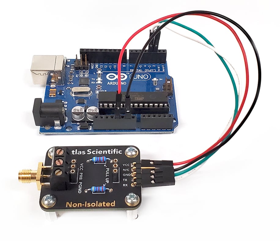
Now that our Arduino Uno is wired correctly, let’s move on to the Carrier board. On the back side of the board, you’ll notice there are pins labeled:
VCC
N/C (not connected)
GND
TX
RX
Start by connecting the other end of the red jumper wire onto the VCC pin. Next, connect the black jumper wire onto the GND pin. Then, connect the green jumper wire onto the TX pin, and finally connect the white jumper wire onto the RX pin.
When complete, it should look like the image below.
Ok, now that our carrier board is all wired up, we need to connect the EZO™ Adapter, which allows you to connect a 5 pin EZO™ Sensor to a 6-pin socket.

Insert the EZO™ Adapter directly into the Carrier board, just like you would do if this were an EZO™ class circuit.

Finally, all that’s left to do, is to connect the EZO-RGB™ Embedded Color Sensor to the EZO™ Adapter. Just slide the sensor connector onto the adapter. There are color indicators on the sides of the EZO™ Adapter, make sure you line it up correctly!

Using the USB cable type, A – B male/male, connect one end into your PC and the other into the Arduino Uno board.
Once the USB cable has been connected at both ends, you will notice the LEDs on the Arduino are now lit up and blinking. Looking at the back of your EZO-RGB™ Embedded Color Sensor, it should also be lit up and blinking.
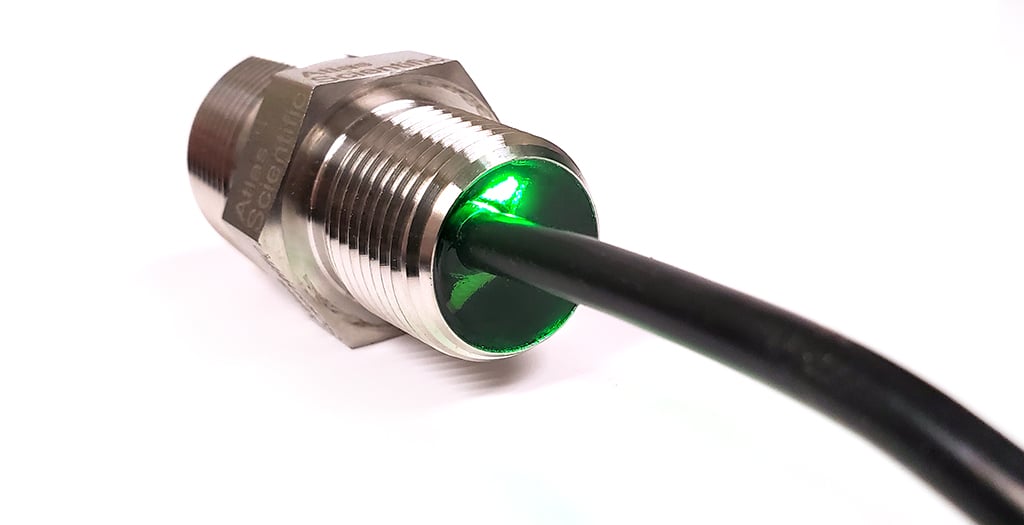
All Atlas Scientific Sensors have two working modes, UART and I2C. Each of these modes are identified by a color. If your sensor is blinking green, you are in UART mode. If the sensor is solid blue, you are in I2C mode.
By default, all Atlas Scientific Sensors should come in UART mode.
However, if your EZO-RGB™ Embedded Color Sensor is solid blue (I2C mode) refer to the Datasheet on how to change modes.
We are all finished with the wiring, now let’s get the sample code.
If you do not already have the Arduino IDE software installed onto your computer, please do so now, as we’ll be using it for the last section of this tutorial. You can download the Arduino IDE software by clicking HERE.
//This code was written to be easy to understand.

//Modify this code as you see fit.
//This code will output data to the Arduino serial monitor.
//Type commands into the Arduino serial monitor to control the EZO-RGB.
//This code was written in the Arduino 1.8.9 IDE
//An Arduino UNO was used to test this code.
//This code was last tested 6/2019


#include <SoftwareSerial.h>                           //we have to include the SoftwareSerial library, or else we can't use it
#define rx 2                                          //define what pin rx is going to be
#define tx 3                                          //define what pin tx is going to be

SoftwareSerial myserial(rx, tx);                      //define how the soft serial port is going to work


String inputstring = "";                              //a string to hold incoming data from the PC
String sensorstring = "";                             //a string to hold the data from the Atlas Scientific product
boolean input_string_complete = false;                //have we received all the data from the PC
boolean sensor_string_complete = false;               //have we received all the data from the Atlas Scientific product


void setup() {                                        //set up the hardware
  Serial.begin(9600);                                 //set baud rate for the hardware serial port_0 to 9600
  myserial.begin(9600);                               //set baud rate for the software serial port to 9600
  inputstring.reserve(10);                            //set aside some bytes for receiving data from the PC
  sensorstring.reserve(30);                           //set aside some bytes for receiving data from Atlas Scientific product
}


void serialEvent() {                                  //if the hardware serial port_0 receives a char
  inputstring = Serial.readStringUntil(13);           //read the string until we see a <CR>
  input_string_complete = true;                       //set the flag used to tell if we have received a completed string from the PC
}


void loop() {                                         //here we go...

  if (input_string_complete == true) {                //if a string from the PC has been received in its entirety
    myserial.print(inputstring);                      //send that string to the Atlas Scientific product
    myserial.print('\r');                             //add a <CR> to the end of the string
    inputstring = "";                                 //clear the string
    input_string_complete = false;                    //reset the flag used to tell if we have received a completed string from the PC
  }

  if (myserial.available() > 0) {                     //if we see that the Atlas Scientific product has sent a character
    char inchar = (char)myserial.read();              //get the char we just received
    sensorstring += inchar;                           //add the char to the var called sensorstring
    if (inchar == '\r') {                             //if the incoming character is a <CR>
      sensor_string_complete = true;                  //set the flag
    }
  }


  if (sensor_string_complete == true) {               //if a string from the Atlas Scientific product has been received in its entirety
    if (isdigit(sensorstring[0]) == false) {          //if the first character in the string is a digit
      Serial.println(sensorstring);                   //send that string to the PC's serial monitor
    }
    else                                              //if the first character in the string is NOT a digit
    {
      print_RGB_data();                               //then call this function
    }
    sensorstring = "";                                //clear the string
    sensor_string_complete = false;                   //reset the flag used to tell if we have received a completed string from the Atlas Scientific product
  }
}


void print_RGB_data(void) {                           //this function will pars the string

  char sensorstring_array[30];                        //we make a char array
  char *red;                                          //char pointer used in string parsing
  char *grn;                                          //char pointer used in string parsing
  char *blu;                                          //char pointer used in string parsing
  int int_red;                                        //used to hold an int that is the color red
  int int_grn;                                        //used to hold an int that is the color green
  int int_blu;                                        //used to hold an int that is the color blue

  sensorstring.toCharArray(sensorstring_array, 30);   //convert the string to a char array
  red = strtok(sensorstring_array, ",");              //let's pars the array at each comma
  grn = strtok(NULL, ",");                            //let's pars the array at each comma
  blu = strtok(NULL, ",");                            //let's pars the array at each comma


  Serial.print("RED:");                                //we now print each value we parsed separately
  Serial.println(red);                                 //this is the red value

  Serial.print("GREEN:");                              //we now print each value we parsed separately
  Serial.println(grn);                                 //this is the green value

  Serial.print("BLUE:");                               //we now print each value we parsed separately
  Serial.println(blu);                                 //this is the blue value

// int_red= atoi(red);                                 //uncomment this line to convert the char to an int
// int_grn= atoi(grn);                                 //uncomment this line to convert the char to an int
// int_blu= atoi(blu);                                 //uncomment this line to convert the char to an int
}
The above code, can be copied and pasted directly into the Arduino IDE software, however you can also download the code by clicking HERE.
Extract the sample code *.ino file and run it. The Arduino IDE software will inform you that the *.ino file needs to be placed within its own sketch folder, just click OK to continue.
We’re almost ready to take readings from the EZO-RGB™ Embedded Color Sensor, but before we do, we must make sure that the Arduino IDE software knows which board we are using. Go to Tools > Board > Arduino AVR Boards > and make sure that Arduino Uno is selected.

Next, you must tell the software which COM port on your computer the Arduino Uno board is connected to. Go to Tools > Port > and choose the correct COM port.
Now that everything has been properly setup, and the code is ready to go, press the upload button (located at the top left) and it will upload the code directly to your Arduino Uno board.
Ok… Final step, here we go!
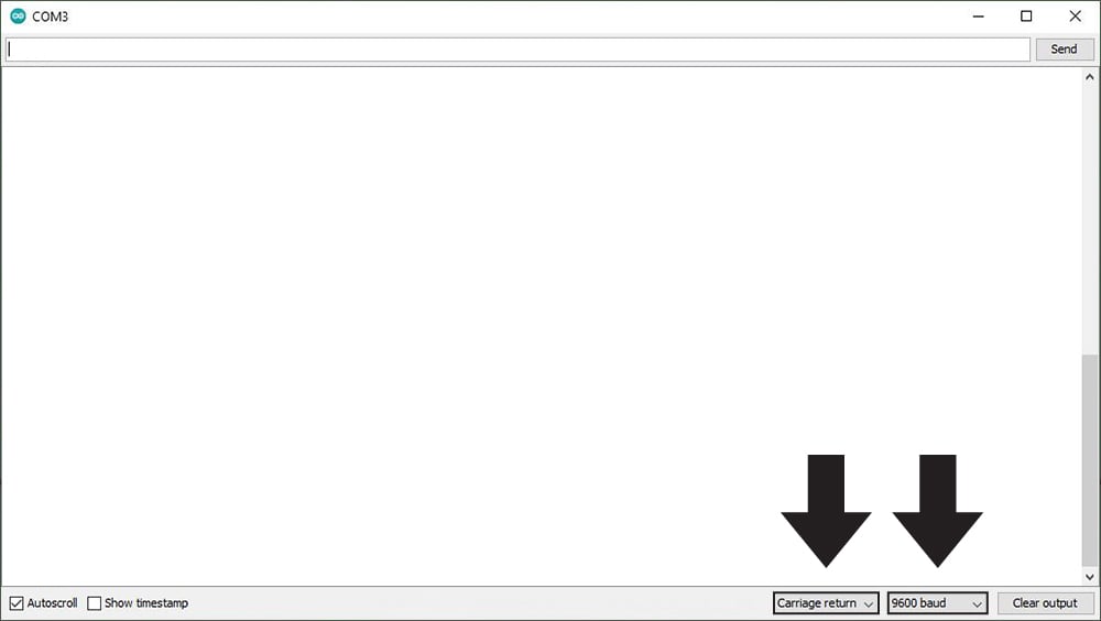
Now, you can start taking readings from the EZO-RGB™ Embedded Color Sensor. From within the Arduino IDE Software, open the Serial Monitor (located at the top right) and make sure to set it to append carriage return only and set the baud rate to 9600.
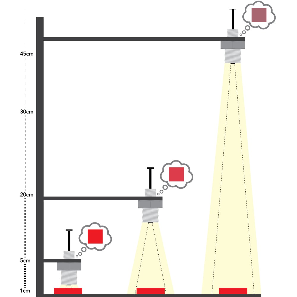
Before we get into the calibration process, there is one important factor to consider when reading color: Distance
As the EZO-RGB™ Embedded Color Sensor is placed further away from the target object, its ability to detect color is diminished. At distances greater than 45cm most colors become varying shades of gray.
The EZO-RGB™ Embedded Color Sensor is designed to be calibrated to a white object at the maximum brightness the object will be viewed under. To get the best results Atlas Scientific strongly recommends that the sensor is mounted into a fixed location. Holding the sensor in your hand during calibration will decrease performance.
1. Embed the Color Sensor into its intended use location.
2. Set LED brightness to the desired level. (refer to the datasheet for adjusting the LED brightness value.)
3. Place a white object in front of the target object and then issue the calibrate command “cal”.
4. A single color reading will be taken, and the device will be fully calibrated.
Congratulations, all the setup work is now complete! You should start to see readings from the EZO-RGB™ Embedded Color Sensor.
For more information on these commands and many others, please refer to the EZO-RGB™ Embedded Color Sensor’s Datasheet.
Of course, if you run into any trouble, our tech support team is always here and ready to help you get the EZO-RGB™ Embedded Color Sensor running in no time!
There are different types of dissolved oxygen sensors, including optical, polarographic, and galvanic. Galvanic sensors are affordable and ready to use right away, but they

Thermocouples, RTDs, and thermistors all measure temperature, but they are better at different things. Thermocouples can handle very high temperatures, thermistors are very sensitive over