Subtotal: $69.99

Blog
Understanding COD in Wastewater Treatment
The amount of oxygen needed to chemically oxidize organic and inorganic materials in wastewater is measured by Chemical Oxygen Demand, or COD. High COD depletes


In this tutorial, we will show you how to connect an Atlas Scientific EZO™ RTD Temperature Circuit and a PT-1000 Temperature Probe to an Arduino Uno. There are multiple ways to connect Atlas Scientific sensors to an Arduino, but for ease of use; we will be using a simple setup that will get our temperature sensor running in UART mode in no time!
There is no shortage of temperature probes out there, and the most accurate of them all is the platinum RTD (Resistance Temperature Detector) probe. However, converting the resistance of platinum to an actual temperature is unusually complicated. Fortunately, the Atlas Scientific EZO™ RTD Circuit makes taking high accuracy readings from a platinum RTD probe easy.
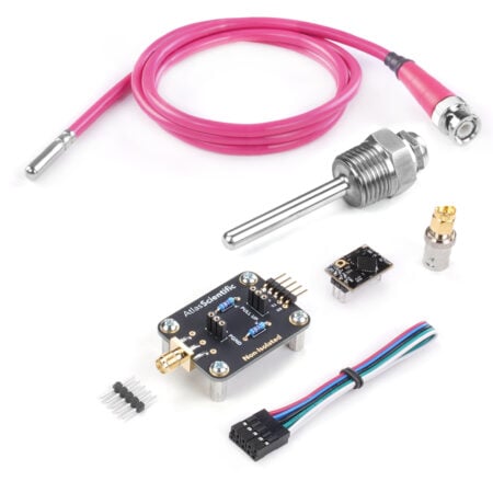
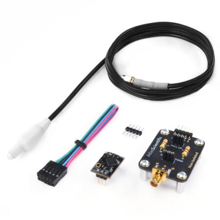
Before we begin have the following items readily available:

When connecting an EZO™ circuit to an Arduino or a Raspberry Pi, try to remember that organization is key, which is why we are using 4 different colored jumper wires. Sure, we all know that Red is VCC and Black is GND. However, over the years we have seen many people use the same-colored jumper wires throughout their entire project. I know, having all the jumper wires in black looks really cool… but it’s very easy to get lost in your own mess. For this tutorial, we are going to use Red, Black, Yellow, and Green.

We are going to follow this wiring diagram. Do not worry, it looks more complicated than it really is!
Let’s start by placing the EZO™ RTD Temperature Circuit into the middle of the breadboard.
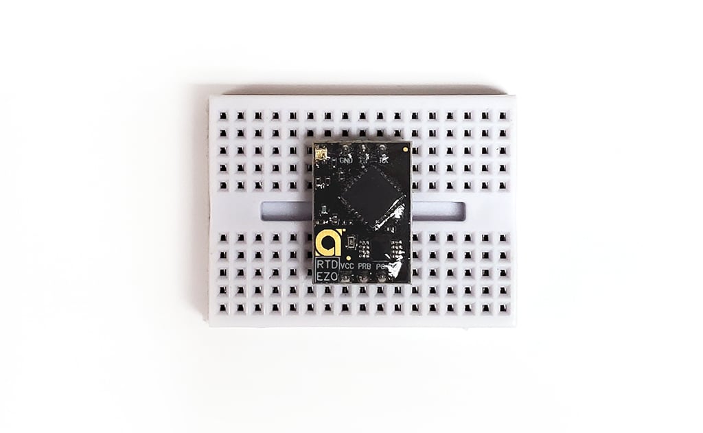
You can use any size breadboard you would like. For this tutorial, I am using a tiny one.
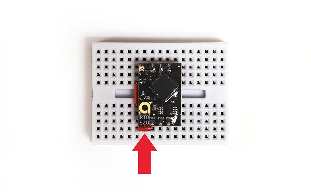
Next, we’re going to place one of the small jumper wires to the left side of the EZO™ RTD Temperature Circuit, so that it bridges the gap in the middle of the breadboard, as shown in the image below.

Once that small jumper wire is in the correct spot, place the second small jumper wire under the VCC pin at the bottom of the EZO™ RTD Temperature Circuit, as shown in the image below. This will extend the VCC line up towards the top of the breadboard.
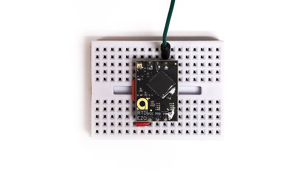
Now that we extended the VCC line, it’s time to connect the jumper wires. Place the green jumper wire in the slot just above the RX pin of the EZO™ RTD Temperature Circuit.
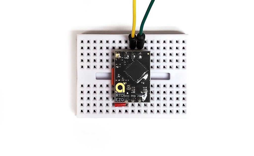
Next, place the yellow jumper wire in the slot just above the TX pin.
Then, place the black jumper wire in the slot just above the GND pin.
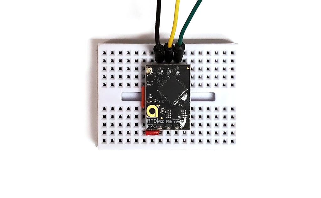
Lastly, place the red jumper wire one slot over to the left, so it lines up with the smaller jumper wire, as shown in the image below.

Alright, we are making good progress, our breadboard and circuit are all wired up. Now, let’s move on to the Arduino Uno.

Let’s start by placing the yellow jumper wire into pin 2 on the Arduino Uno board.
Then, place the green jumper wire into pin 3 on the Arduino Uno board.
These two jumper wires are important as they will allow both the EZO™ RTD Temperature Circuit and the Arduino Uno board to communicate with each other.
Next, place the red jumper wire into the 5V pin. And finally, place the black jumper wire into any of the 2 GND or ground pins near the 5V pin.
These two jumper wires will supply power and a ground line from the Arduino Uno to the EZO™ RTD Temperature Circuit.
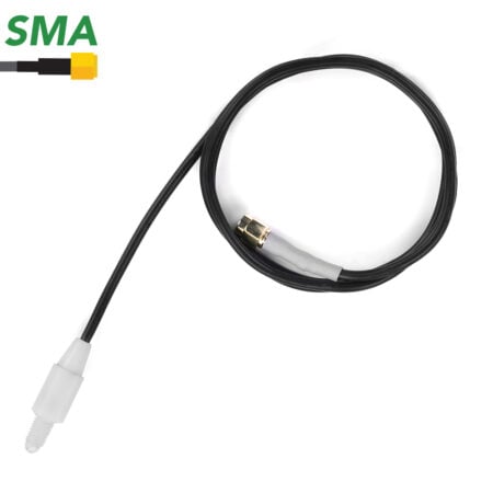
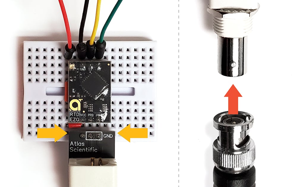
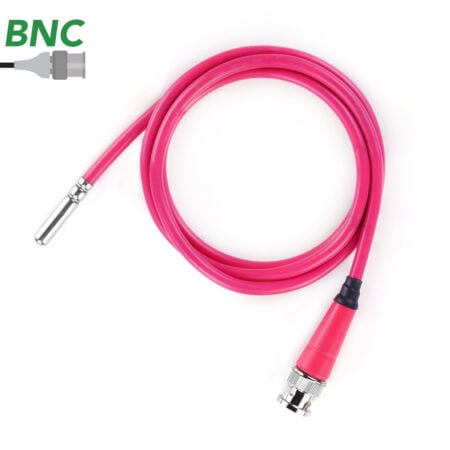
Now that all four of the jumper wires have been connected, we are ready for the Pre-assembled Female BNC. Place it on the breadboard such that the pins highlighted by the white rectangle line up with the PRB and PGND pins on the EZO™ RTD Temperature Circuit. Then, connect the PT-1000 temperature probe to the BNC.
Using the USB cable type A – B male/male, connect one end into your PC and the other into the Arduino Uno board.
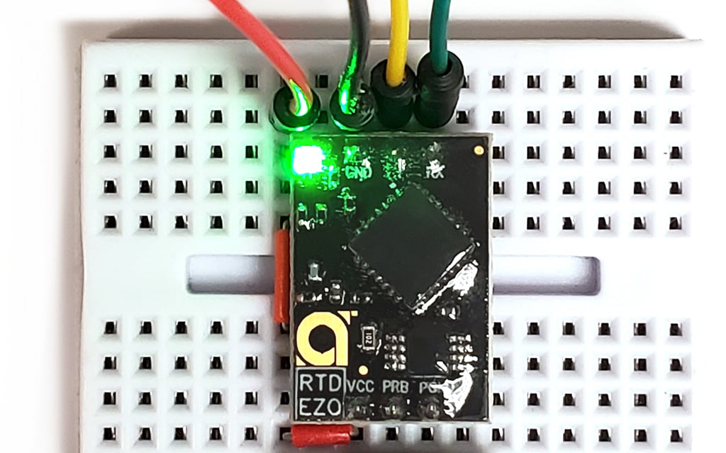
Once the USB cable has been connected at both ends, you will notice the LEDs on the Arduino are now lit up and blinking. The EZO™ RTD Temperature Circuit should also be lit up and blinking.
We are all finished with the wiring, now comes the fun part.
Side Note
All Atlas Scientific Sensors have two working modes, UART and I2C. Each of these modes are identified by a color. If your EZO circuit is blinking green you are in UART mode. If the circuit is showing a solid blue, you are in I2C mode.
By default, all Atlas Scientific Sensors should come in UART mode.
However, if your EZO™ RTD Temperature Circuit is a solid blue (I2C mode) refer to the Datasheet on how to change modes.
If you do not already have the Arduino IDE software installed onto your computer, please do so now, as we will be using it for the last section of this tutorial. You can download the Arduino IDE software by clicking HERE.
Next, we need to get the Arduino Uno Sample code, instead of writing it all out, let’s just download it from our website. Click HERE to download the code!
Extract the sample code *.ino file and run it. The Arduino IDE software will inform you that the *.ino file needs to be placed within its own sketch folder, just click OK to continue.
You should now be in the Arduino IDE software.
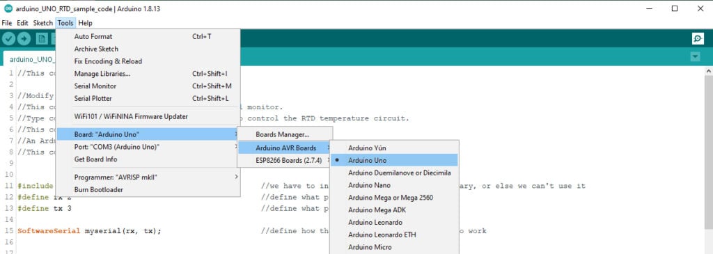
We’re almost ready to take readings from the EZO™ RTD Temperature Circuit, but before we do, we must make sure that the Arduino IDE software knows which board we are using. Go to Tools > Board > Arduino AVR Boards > and make sure that Arduino Uno is selected.
Finally, you must tell the software which COM port on your computer the Arduino Uno board is connected to. Go to Tools > Port > and choose the correct COM port.
Now that everything has been properly set up, and the code is ready to go, press the upload button (located at the top left) and it will upload the code directly to your Arduino Uno board.
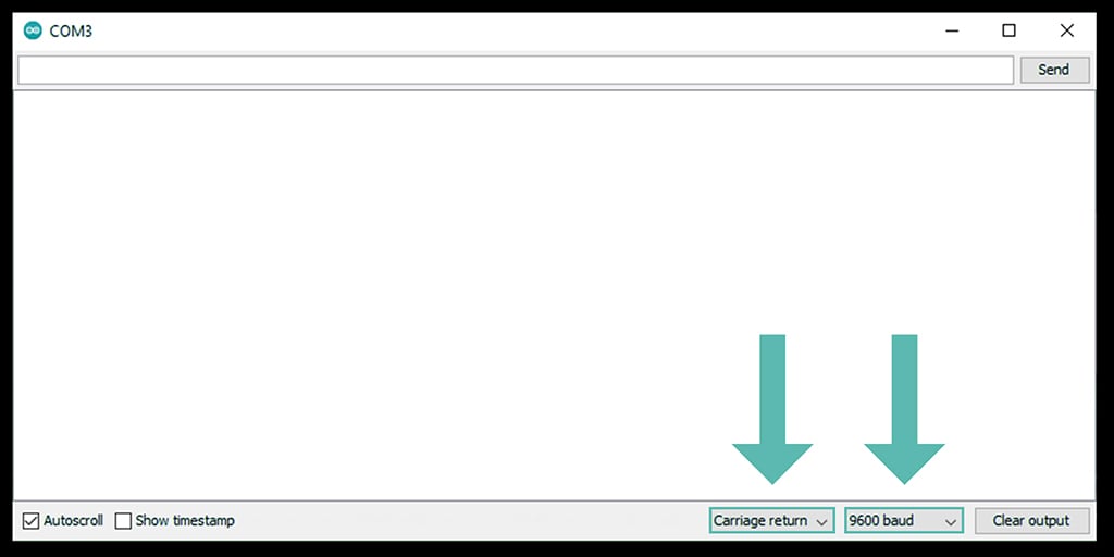
From within the Arduino IDE Software, open the Serial Monitor (looks like a magnifying glass located at the top right) and make sure to set it to append carriage return only and set the baud rate to 9600. Now, you can start taking readings from the EZO™ RTD Temperature Circuit.
Calibration can be done at any value; a simple method is to calibrate the probe in boiling water. The boiling point of water is 100 ℃ (depending on your altitude).
Place the PT-1000 probe in a beaker of water and bring the water to a boil. Watch the readings within the Serial Monitor, and once they hit 100 calibrate to that temperature by entering:
Cal,100 (press enter)
The EZO™ RTD Temperature Circuit will respond with: *OK.
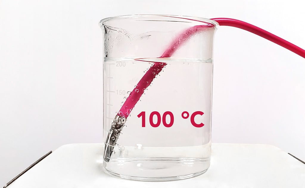
The EZO™ RTD Temperature Circuit has been calibrated and you are now ready to take temperature readings!


The amount of oxygen needed to chemically oxidize organic and inorganic materials in wastewater is measured by Chemical Oxygen Demand, or COD. High COD depletes

An RDWC (Recirculating Deep Water Culture) system connects multiple deep water culture sites into one continuously circulating nutrient loop, creating a single, shared root zone.