

Blog
The Best Indoor Air Quality Monitors
Indoor air quality can have a major impact on the comfort and productivity of homes, offices, schools, laboratories, and industrial facilities. Carbon dioxide buildup, poor





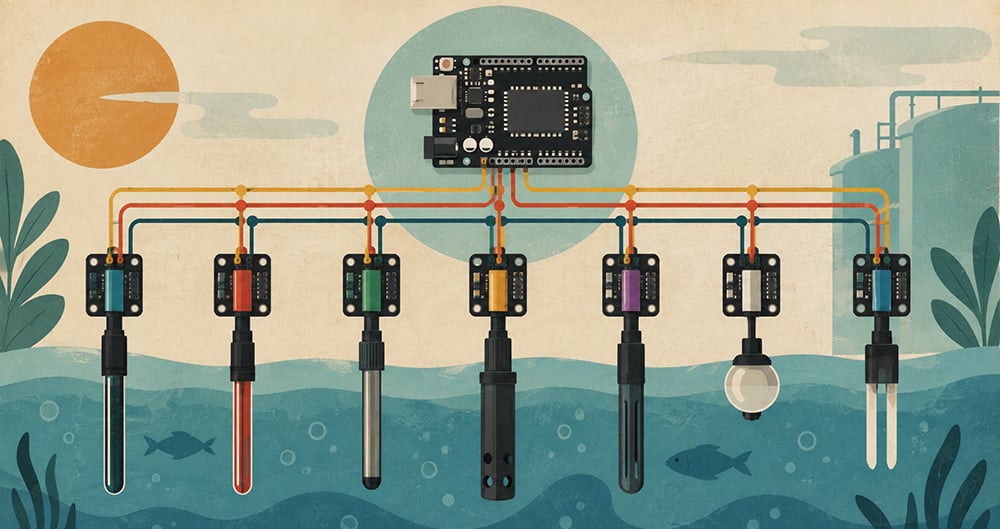
I2C allows multiple sensors and devices to talk to a single microcontroller using just two wires. That elegance is what has made it a staple in embedded systems, scientific instruments, and environmental monitoring equipment for over four decades.
If you’ve ever connected a sensor to a microcontroller, you’ve probably used I2C, even if you didn’t realize it at the time. That’s one of the most-used communication protocols in electronics, and there’s a reason for that.
In this article, we’ll cover what I2C is, how it works, why it was designed the way it was, and why it’s still such a popular choice for sensor communication, including in many of Atlas Scientific’s own sensors and circuits.
I2C is short for Inter-Integrated Circuit. It was developed in 1982 by Philips Semiconductor (now NXP) as a way for chips in the same device to communicate with each other without a tangle of wires. The name says it all: it was designed for communication between integrated circuits on the same board.
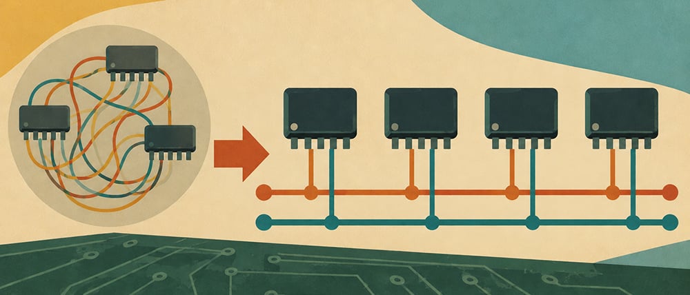
The original specification supported communication speeds up to 100 kHz and used a 7-bit addressing system, which allowed up to 112 unique devices to share the same bus. The protocol has continued to evolve since 1992, when Philips released a public specification that added a faster 400 kHz mode and expanded addressing.
Since 2006, implementing I2C has required no license, which opened the floodgates. Today, thousands of chips from hundreds of manufacturers support I2C, from temperature sensors and pressure gauges to display drivers and real-time clocks. It has become one of the lingua francas of the electronics world.
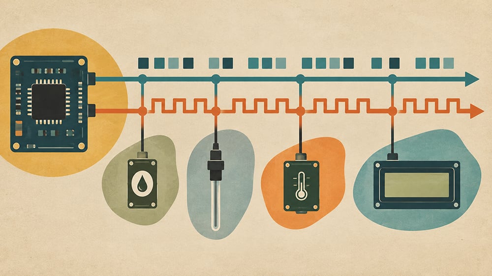
The defining characteristic of I2C is its simplicity at the hardware level. Every device on an I2C bus shares just two signal lines:
SDA (Serial Data Line) carries the actual data, the bytes of information being sent and received between devices.
SCL (Serial Clock Line) carries a clock signal that keeps every device on the bus in sync. The controller device generates this clock, and all other devices on the bus use it to time their communication.
That’s it. Two shared signal lines that you can connect a lot of devices to a single microcontroller. For comparison, a typical 7-bit I2C system can support up to 112 devices sharing the same two wires (some addresses are reserved for special functions). 10-bit addressing expands the theoretical address space into the thousands of possible addresses, although practical systems are usually limited by electrical considerations long before reaching that scale.
Now look at the other options, where every new device needs a separate chip-select line from the controller, and the beauty of I2C should become immediately obvious. Two wires, regardless of how many devices you connect. That’s a big practical advantage for sensor-heavy applications where space, wiring complexity, and cost are all important.
Every I2C system has at least one controller (sometimes called a master) and one or more peripherals (sometimes called slaves, though this terminology is increasingly being replaced). The controller is the device that initiates all communication and generates the clock signal. The peripherals respond when addressed.
In a typical embedded system, the microcontroller acts as the controller, and the sensors connected to it act as peripherals. The controller decides when to communicate, which device to talk to, and whether it wants to read data from or write data to that device. Peripherals sit quietly on the bus until they hear their address, at which point they respond.
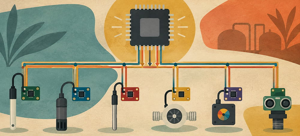
Importantly, I2C supports multiple controllers on the same bus. This is useful in more complex systems where two microcontrollers might both need access to the same set of sensors. There are built-in arbitration mechanisms to prevent conflicts when two controllers try to use the bus simultaneously, but in most practical sensor applications, a single controller is all you need.
Understanding the communication sequence helps clarify how data is exchanged across an I2C interface. Although the protocol uses only two signal lines, it provides a structured and reliable method for communication between a controller and multiple peripheral devices.
Every I2C transaction begins with a Start condition. This occurs when the controller pulls the SDA (Serial Data) line low while the SCL (Serial Clock) line remains high. This defined transition signals the beginning of a communication session and alerts all connected devices that a transmission is about to start.
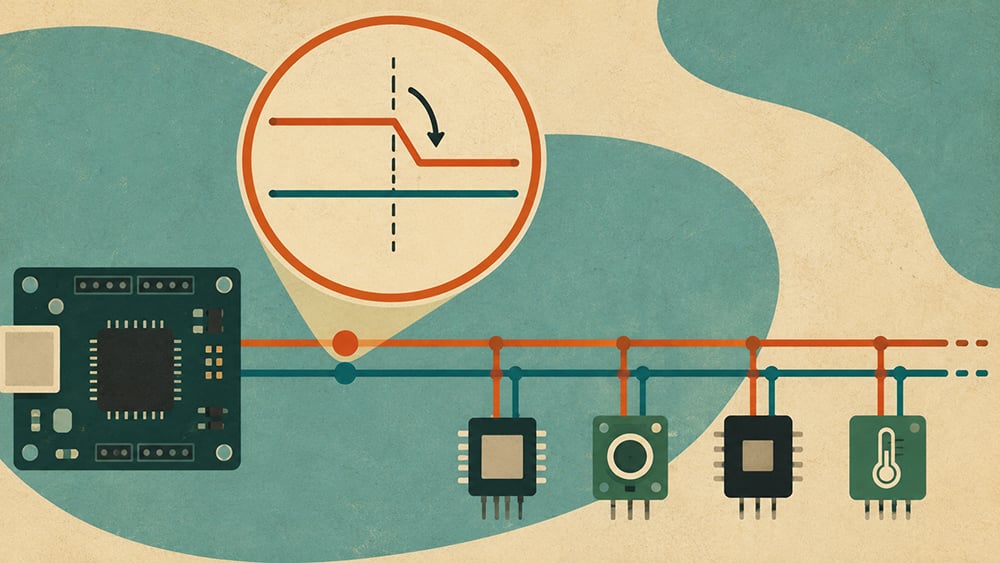
Following the Start condition, the controller transmits a 7-bit device address. This address identifies the specific peripheral device involved in the transaction. Because each device connected to the I2C interface is assigned a unique address, multiple devices can share the same communication lines without ambiguity.
After the address, the controller transmits a single Read/Write (R/W) bit. This bit indicates whether the controller intends to write data to the addressed device or read data from it.
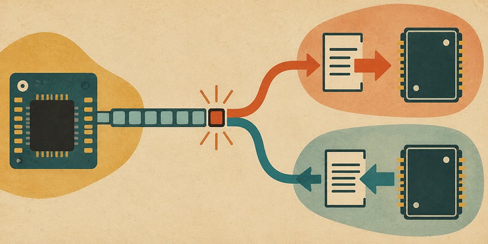
All connected devices receive the address information, but only the device with the matching address responds. It acknowledges the request by pulling the SDA line low during the ninth clock cycle, generating an ACK (Acknowledge) signal. If no acknowledgment is received, the controller can determine that the addressed device is unavailable or that a communication error has occurred.
Once communication has been established, data is transferred in 8-bit frames (bytes). After each byte, the receiving device normally generates an ACK. During a read operation, this means the controller acknowledges bytes received from the peripheral and typically sends a NACK after the final byte to indicate that the transfer is complete.
This acknowledgment mechanism provides an important layer of reliability. Rather than allowing communication failures to go undetected, missing acknowledgments immediately indicate that data was not received as expected, enabling the controller to initiate error-handling or retry procedures.
When the transaction is complete, the controller generates a Stop condition by allowing SCL to remain high and transitioning SDA from low to high. This sequence signals the end of the communication session and releases the bus, making it available for subsequent transactions.
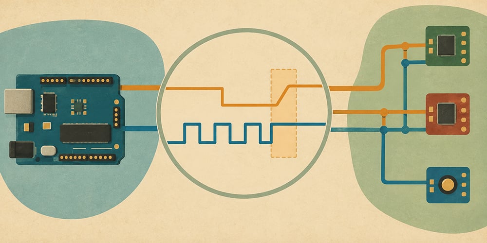
One of the more elegant things about I2C is how it avoids destructive collisions on the bus. If two devices tried to drive the same wire to opposite states at the same time, say one pushing it high and the other pulling it low, then you could get a short circuit, damaged components, or corrupted data.
I2C avoids this by a design principle called open-drain output. I2C devices can only pull the line low, not actively drive the bus high. Each line has a pull-up resistor to keep it high when no device is pulling it low. This means that if two devices both claim the bus at the same time, the worst that happens is the line goes low – which is a defined, safe state.
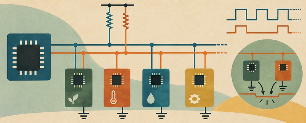
This is also what allows I2C to be bidirectional on a single wire. The controller can pull SDA low to transmit data, and the peripheral can pull it low to send an ACK or return data. The communication is organised because both sides are only ever pulling low – never fighting to drive high against each other.
The pull-up resistors themselves are a small but significant design detail. If resistance is too high, the bus will charge too slowly, and speed will be limited. Too low and you have more power consumption. One of the practical issues you will encounter when designing an I2C circuit is getting the resistor values right for the bus speed and capacitance of your particular system.
Over the years, the demand for faster communication grew; therefore, additional speed modes were defined.
Standard Mode operates at up to 100 kHz and is the original specification. It is supported by virtually every I2C device ever made and is more than sufficient for most sensor reading applications where data doesn’t need to change thousands of times per second.
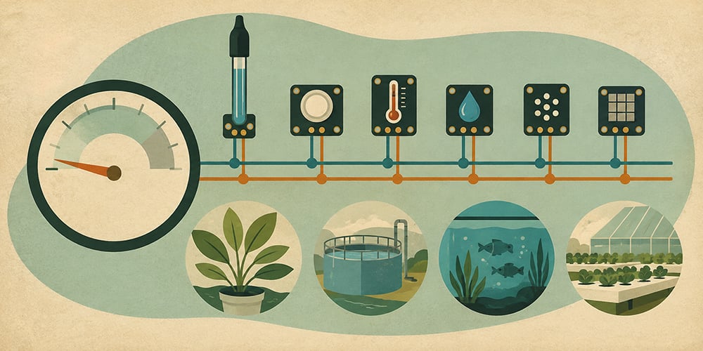
Fast Mode extends the maximum speed to 400 kHz. This is widely supported and a common choice when slightly higher throughput is needed. For example, when polling multiple sensors rapidly or when combined with display drivers.
Fast Mode Plus allows speeds up to 1 MHz. This requires stronger pull-down current capability in the devices and is less universally supported, but is useful in more demanding applications.
High-Speed Mode and Ultra-Fast Mode push communication to 3.4 MHz and 5 MHz, respectively. These are specialist modes for high-performance applications and are not commonly encountered in sensor work.
For the kinds of applications Atlas Scientific sensors are used in water quality monitoring, environmental sensing, laboratory measurement, Standard or Fast Mode is almost always the right choice. Sensor readings simply don’t change fast enough to require anything faster.
What makes I2C scale so well is the addressing system. Each peripheral on an I2C bus needs a unique address. Some I2C devices use fixed addresses or hardware address pins, while others allow their address to be configured in software. Atlas Scientific EZO™ circuits use configurable I2C addresses, making it possible to connect multiple circuits, even multiple circuits of the same type, to a single I2C bus by assigning each one a unique address.
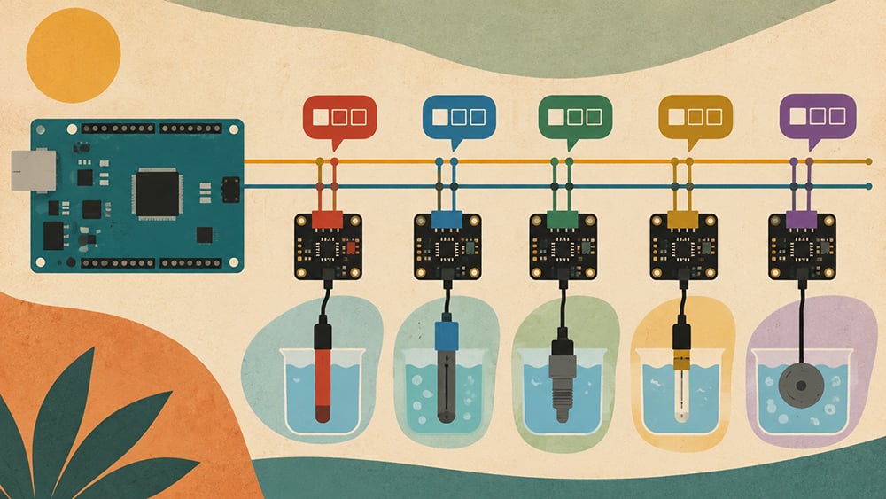
Some devices allow the address to be changed by connecting an address pin to VCC or GND, which gives a small number of address options for a given chip. Some have a factory-set fixed address. When designing a system that uses an I2C bus to connect several devices, it is important to make sure that each of the sensors has a different address.
For example, a system might combine an EZO™ pH Circuit, EZO™ Conductivity Circuit, and EZO™ Dissolved Oxygen Circuit on the same I2C bus, each with its own address.
EZO-pH: 99 (0x63)
EZO-EC: 100 (0x64)
EZO-DO: 97 (0x61)
I2C is a nice sweet spot for the particular job of attaching sensors to a microcontroller. It does not require the number of wires that other protocols require, making it practical in tight enclosures and devices where routing many signal lines would be difficult. Multiple peripheral support enables a single microcontroller to control a whole sensor array without additional hardware.
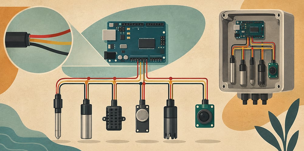
The acknowledgement-based protocol also means that the controller always knows if a sensor has responded or not, which is valuable in applications where a failed sensor reading could lead to incorrect conclusions about water quality, process conditions, or environmental state.
Perhaps more importantly, the software overhead is low. Most microcontroller platforms have I2C support built into their hardware peripherals, and well-maintained libraries handle the low-level details of start conditions, addressing, and ACKs automatically. Getting a sensor to talk over I2C generally involves a few lines of setup code and a read command, not the sort of complex implementation that used to require deep expertise to handle.
For embedded systems with multiple devices that need to share a communication bus without excessive wiring, I2C is still one of the most practical choices out there. That is why many of the Atlas Scientific EZO™ circuits have native support for I2C. Because in the real world, clean, reliable, multi-sensor communication matters.
If you have questions about integrating Atlas Scientific sensors into an I2C system, or want to know which circuit boards support I2C in your application, contact the world-class team at Atlas Scientific. We’re here to help you build something that works for you.
Indoor air quality can have a major impact on the comfort and productivity of homes, offices, schools, laboratories, and industrial facilities. Carbon dioxide buildup, poor
UART and I2C are serial communication protocols, but they serve different purposes. UART is typically used for direct device-to-device communication and requires dedicated connections. I2C