

Blog
What is a 4 – 20mA Current Loop?
The 4-20mA current loop is the dominant analog signaling method in industrial process control. It transmits sensor measurements, such as temperature, pressure, pH, and flow,





The 4-20mA current loop is the dominant analog signaling method in industrial process control. It transmits sensor measurements, such as temperature, pressure, pH, and flow, as a varying electrical current between 4 and 20 milliamps. Because it uses current rather than voltage, it is highly resistant to electrical noise, works reliably over long cable runs, and can immediately flag a wiring fault.
Today, thousands of sensors continually feed critical values such as temperature, pressure, pH, flow, and level back to a central control system that maintains process efficiency and safety. And while the sophisticated digital communication protocols may be doing a lot of the communication work in many modern industrial plants, there is a remarkably simple device, the 4-20mA current loop. This has become the industry standard over the years, and it is here to stay for the foreseeable future due to its reliable, noise-resistant, easy-to-troubleshoot ability to transmit a clear signal over relatively long distances.

So what is a 4-20mA current loop, how does it work, and why has it persisted despite all of the modern digital options available to us?
The 4-20mA current loop is the most widely used analogue signal standard for industrial automation and process control. It sends sensor measurements including temperature, pressure, pH, flow rate, and dissolved oxygen as a proportional electrical current of 4 to 20 milliamps.
The 4-20mA signal is a current, not a voltage. This makes it very immune to electrical noise, stable over long cable distances, and instantly shows wiring faults. For more than 50 years, these benefits have made it the standard of choice in water treatment, chemical processing, manufacturing, energy systems, and building automation.
Digital industrial protocols such as Modbus and HART are gaining in popularity, but the 4-20mA current loop remains the backbone of industrial sensor communication worldwide.
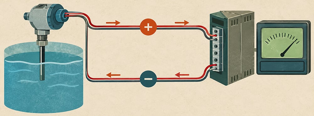
A 4–20mA current loop is a simple two-wire or four-wire analog communication method where a sensor transmitter controls the current flowing through a closed electrical loop.
The measured process variable is represented by a proportional current:
For example, in a 0–100°C temperature range:
| Temperature | Current Output |
| 0°C | 4mA |
| 25°C | 8mA |
| 50°C | 12mA |
| 75°C | 16mA |
| 100°C | 20mA |
Because the loop is a series circuit, the same current flows through every device, regardless of cable length or resistance.
The key advantage of a current loop is its immunity to voltage drop.
Using Ohm’s Law:
V = I × R
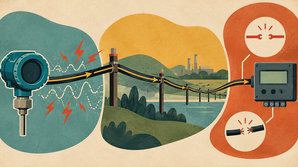
In voltage-based systems, cable resistance causes a voltage drop at the receiving end, which can introduce measurement error over long distances. This makes voltage signals more susceptible to error over long cable runs and in electrically noisy industrial environments, but they remain reliable for short-distance applications such as building automation. In a 4-20mA system, the transmitter regulates current within a defined compliance voltage range, adjusting its internal drive circuitry to maintain the correct loop current regardless of cable resistance (within system limits). Cable resistance does not affect signal accuracy as long as the transmitter remains within its compliance voltage range and the loop is properly designed.
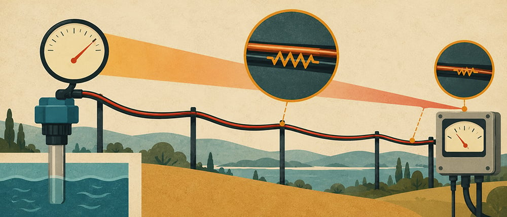
A good analogy is the fluid flow in a pipe:
The flow rate is constant because the longer pipe is compensated by the pump that overcomes the resistance. This is why 4-20mA signals can reliably be used over distances of 1,000 meters or more in properly designed loops with adequate supply voltage and controlled total loop resistance.
A defining feature of the 4-20mA standard is the use of 4mA as the minimum signal instead of 0mA.
This creates a critical diagnostic advantage:
Without this distinction, it would be impossible to differentiate between a true zero reading and a system failure. The live zero ensures that any loss of signal immediately indicates a fault, enabling fast troubleshooting without additional diagnostics.
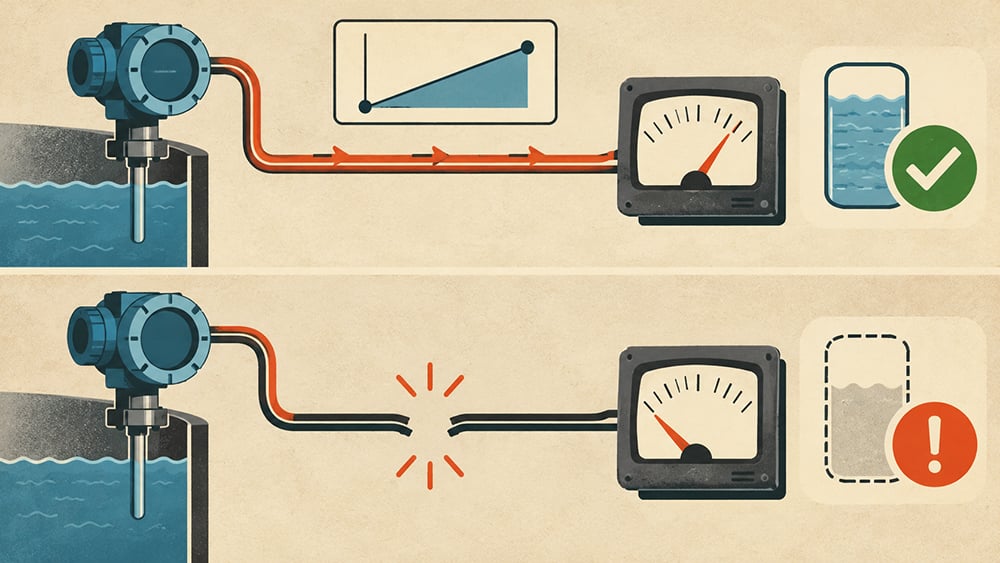
A full 4-20mA current loop consists of five basic elements in series:
The sensing element measures a physical parameter such as pH, temperature, or pressure. In many modern instruments, the sensing and signal conditioning electronics are integrated into a single transmitter assembly that produces the 4–20 mA output.
The transmitter converts the sensor measurement into a proportional 4-20mA output signal. In many industrial instruments, the sensor and transmitter are combined in one unit.
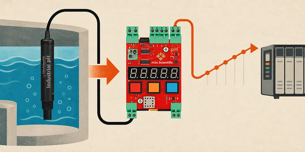
A DC power supply, usually 24VDC, powers the loop. The voltage has to be high enough to cover every loss in the loop, from the wiring and load resistance to the transmitter. As a rule of thumb, add 10 to 20% extra space above the total voltage drop for the loop.
The loop is wired as a simple series circuit using twisted-pair cabling. Cable resistance becomes increasingly important over long distances (typically above 300–500 metres) and must be included in system design calculations.
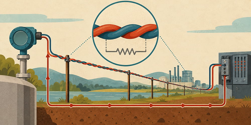
The receiver (PLC, DCS, data logger, or display system) interprets the current signal. In many systems, a precision resistor, commonly 250Ω, is used to convert loop current into a measurable voltage signal for PLC or DAQ inputs:
This allows standard analog inputs to read the process variable.
Two-wire transmitters are directly powered from the current loop itself. The 4-20mA signal supplied both measurement data and power.
This transmitter requires minimal wiring, has a lower installation cost, is ideal for remote field instrumentation, and is very reliable in long cable runs. These advantages are why they are the most common configuration in industrial process control.
Four-wire transmitters use a separate power supply for internal electronics, independent of the signal loop.
They have higher available power for complex electronics and better performance for advanced analyzers. Four-wire transmitters also have independent power and signal design, which is why they are commonly used for analytical instruments and higher-power sensing systems.
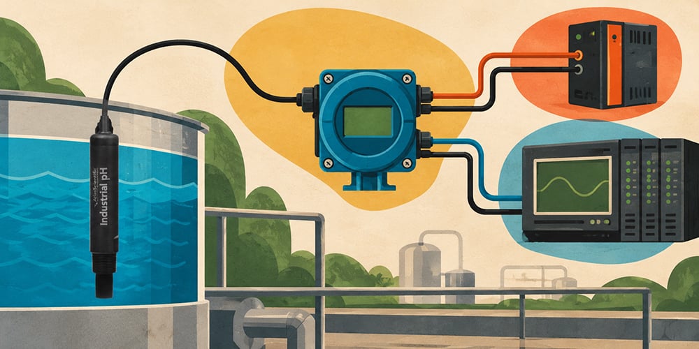
High noise immunity: Current-based signaling is resistant to electromagnetic interference, making it ideal for environments with motors, drives, and heavy electrical equipment.
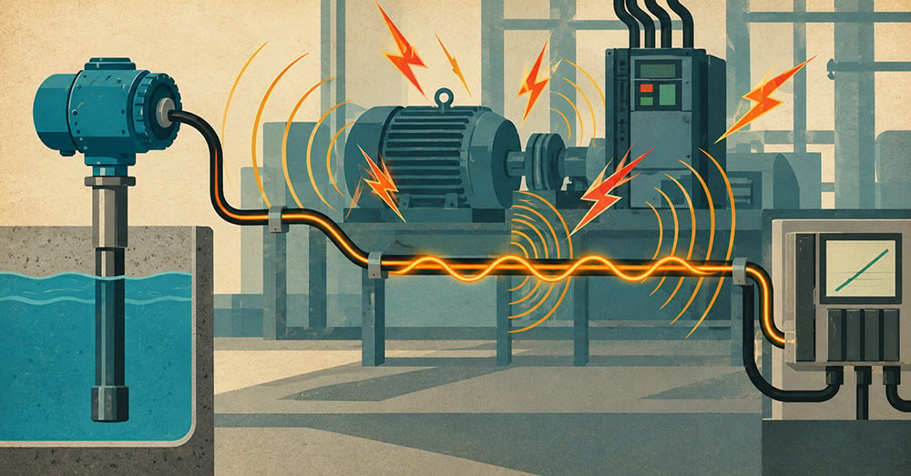
Long-distance transmission: Signals can remain stable over distances exceeding 1,000 metres when the loop is properly designed with sufficient supply voltage, appropriate cable gauge, and total resistance within transmitter compliance limits.
Built-in fault detection: The live zero ensures immediate detection of open circuits or device failure.
Universal compatibility: Supported by nearly all PLCs, DCS systems, and industrial controllers.
Simple installation and diagnostics: Basic tools such as a multimeter can be used to verify loop performance.
Single variable per loop: Each loop carries only one measurement, increasing wiring requirements in large systems.
Loop power constraints: Two-wire devices must operate within limited power budgets.
Wiring scale in large installations: Systems with many sensors require significant cabling infrastructure.

While both signals are common analog standards, their performance differs quite significantly.
| Feature | 4–20mA | 0–10V |
| Noise immunity | High | Moderate to low |
| Maximum cable length | 1,000m+ | Typically <100m |
| Fault detection | Yes (live zero) | No |
| Sensitivity to cable resistance | Low | High (especially over long runs due to voltage drop) |
| Industrial use | Process control | Building automation |
For industrial environments, 4-20mA is often used due to its robustness and fault detection capability.
Many PLCs and microcontrollers use voltage inputs rather than current inputs. A simple resistor allows conversion:
Most common value: 250Ω
Alternative configurations:
The resistor must be selected so the total voltage drop remains within the available loop supply.
0mA reading: Indicates an open circuit, broken wire, or failed transmitter.
Signal fixed at 4mA: Typically indicates sensor failure or loss of input signal.

Signal saturated at or near 20mA: May indicate range limits, wiring faults, or process overload.
Noisy or unstable signal: Often caused by electromagnetic interference or improper grounding. A shielded cable grounded at one end is recommended.
Drifting or inaccurate readings: Usually caused by insufficient supply voltage or excessive loop resistance.
Atlas Scientific industrial Transmitters use 4-20mA for direct integration with SCADA water treatment systems, PLCs, and industrial controllers.
For example, the Atlas Scientific Industrial pH Transmitter supports a measurement range of 0 to 14 pH, with high resolution and accuracy that can reach ±0.002 pH under ideal calibration and controlled conditions. In real-world industrial environments, accuracy depends on calibration quality, temperature compensation, and sensor maintenance.
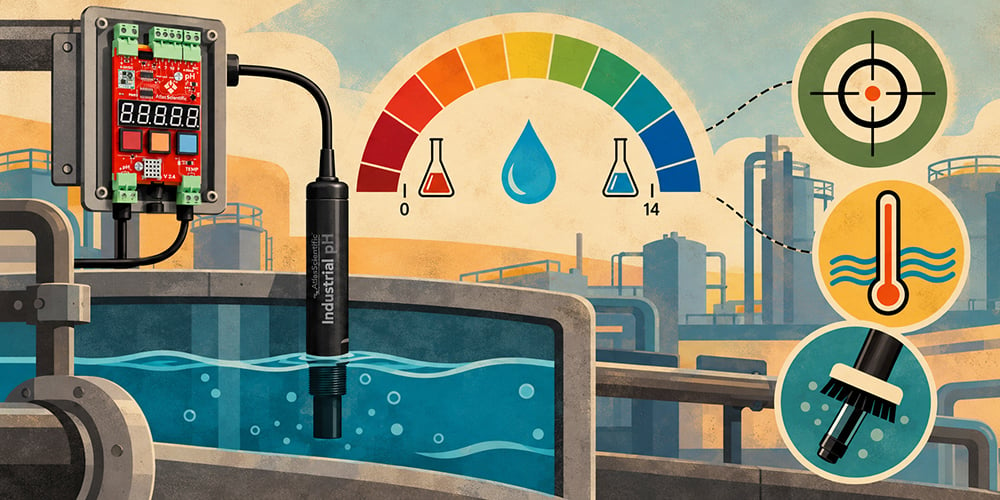
Despite advances in industrial communication protocols such as Modbus, PROFIBUS, and HART, the 4–20mA current loop remains the most widely deployed analog signal in industrial automation.
Its continued dominance is due to a combination of:
For engineers designing or maintaining industrial control systems, understanding the 4-20mA current loop remains essential.
The 4-20mA current loop is a mainstay in industrial sensor communication, and it’s easy to see why. Even after more than 50 years, it still wins in process control because it handles interference well, works over long distances, spots faults on its own, and fits almost any system, so you get accurate results and keep running without downtime.
Whether you’re checking pH in water treatment, tracking dissolved oxygen in a bioprocess, or measuring pressure on a chemical line, the 4-20mA standard delivers a dependable signal over long cable runs, even with electrical noise, and without complicated setup.
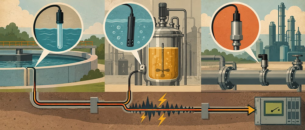
Atlas Scientific’s industrial transmitters convert measurements from compatible probes into standard 4–20 mA signals for PLCs and industrial control systems. This allows straightforward integration without additional signal conversion hardware when the controller has a compatible analog current input.
If you need help wiring Atlas Scientific sensors into a 4–20mA loop, or you’re unsure which instrument fits your job, contact the world-class team at Atlas Scientific anytime. We’re ready to help you.
The 4-20mA current loop is the dominant analog signaling method in industrial process control. It transmits sensor measurements, such as temperature, pressure, pH, and flow,

An oxygen sensor is a device that measures the concentration of oxygen, either dissolved in water or present in gas. It converts the measurement into